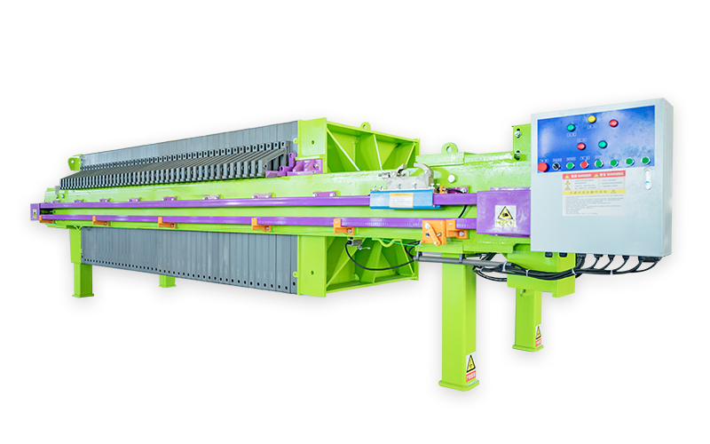
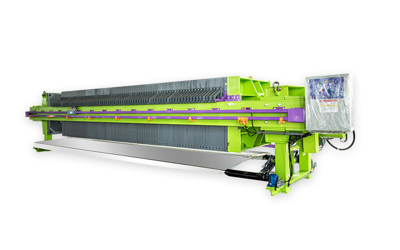
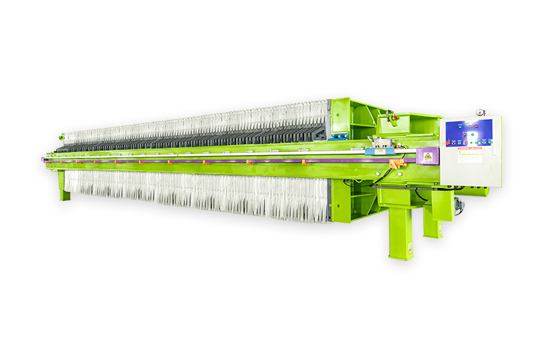
The structure of a filter press consists of three parts
Rack
The rack is the basic component of a filter press. Thrust plates and clamping heads are located at both ends, connected by large beams on either side. These beams support the filter plates, filter frames, and pressure plates. To meet hygiene requirements, the rack needs to be covered with stainless steel. Stainless steel covering techniques can be referenced; their quality meets the needs of European customers.
A. Thrust Plate: It connects with the support to place one end of the filter press on the foundation. In a chamber filter press, the center of the thrust plate has an inlet, and there are four holes in the four corners. The upper two corner holes are for the inlet of washing liquid or compressed gas, and the lower two are for the outlet (whether it's a dark flow structure or filtrate outlet).
B. Pressure Plate: Used to press the filter plates and frames together. The rollers on both sides support the pressure plate's movement on the beam's track.
C. Large Beam: This is a load-bearing component. Depending on the corrosion resistance requirements of the operating environment, it can be coated with rigid polyvinyl chloride, polypropylene, stainless steel, or new anticorrosion coatings.
Clamping Mechanism
Manual clamping, mechanical clamping, hydraulic clamping.
A. Manual Clamping: Uses a spiral mechanical jack to push the pressure plate and clamp the filter plates.
B. Mechanical Clamping: The clamping mechanism consists of a motor (equipped with an advanced overload protector), reducer, gear pair, screw, and fixed nut. During clamping, the motor rotates forward, driving the reducer and gear pair, causing the screw to rotate in the fixed nut, pushing the pressure plate to clamp the filter plates and frames. As the clamping force increases, the motor load current increases. When it reaches the current value set by the protector, the maximum clamping force is achieved, the motor power is cut off, and it stops rotating. Due to the reliable self-locking helical angle of the screw and fixed nut, the clamping state during the working process is reliably ensured. When retracting, the motor reverses, and the retraction stops when the pressure block on the pressure plate touches the limit switch.
C. Hydraulic Clamping: The hydraulic clamping mechanism consists of a hydraulic station, cylinder, piston, piston rod, and a Havalon card connecting the piston rod to the pressure plate. The structure of the hydraulic station includes: motor, oil pump, overflow valve (pressure adjustment), reversing valve, pressure gauge, oil circuit, and oil tank. During hydraulic clamping, the hydraulic station supplies high-pressure oil, and the component chamber formed by the cylinder and piston is filled with oil. When the pressure exceeds the frictional resistance of the pressure plate's movement, the pressure plate slowly clamps the filter plates. When the clamping force reaches the pressure value set by the overflow valve (indicated by the pressure gauge pointer), the filter plates and frames (plate-and-frame type) or filter plates (chamber type) are clamped, and the overflow valve begins to unload. At this time, the motor power is cut off, and the clamping action is complete. For retraction, the reversing valve changes direction, and the pressure oil enters the rod chamber of the cylinder. When the oil pressure can overcome the frictional resistance of the pressure plate, the pressure plate begins to retract. When hydraulic clamping automatically maintains pressure, the clamping force is controlled by an electrical contact pressure gauge. The upper and lower limit pointers of the pressure gauge are set to the values required by the process. When the clamping force reaches the upper limit of the pressure gauge, the power is cut off, and the oil pump stops supplying power. Due to possible internal and external leakage in the oil circuit system causing the clamping force to decrease, when it drops to the lower limit pointer of the pressure gauge, the power is turned on, and the oil pump starts supplying oil. When the pressure reaches the upper limit, the power is cut off, and the oil pump stops supplying oil. This cycle ensures the clamping force during the filtration process.
Filtration Mechanism
The filtration mechanism consists of filter plates, filter frames, filter cloth, and pressure membranes. The filter plates are covered with filter cloth on both sides. When a pressure membrane is required, a set of filter plates consists of a diaphragm plate and a side plate. The base plate of the diaphragm plate is covered with a rubber diaphragm on both sides, and the outside of the diaphragm is covered with filter cloth. The side plate is an ordinary filter plate. The material enters the filter chambers through the material inlet on the thrust plate. Solid particles, whose particle size is larger than the pore size of the filter medium (filter cloth), are retained in the filter chamber, and the filtrate flows out from the outlet below the filter plate. When the filter cake needs to be dewatered, in addition to membrane pressing, compressed air or steam can also be used. It is introduced from the washing port, and the airflow removes water from the filter cake to reduce the moisture content of the filter cake.
(1) Filtration Method
The methods for filtrate outflow are bright flow filtration and dark flow filtration.
A. Bright Flow Filtration: A faucet is installed on the outlet below each filter plate, and the filtrate flows out directly from the faucet.
B. Dark Flow Filtration: An outlet channel is set below each filter plate. The outlet holes of several filter plates are connected to form an outlet channel, which is discharged through a pipe connected to the outlet hole below the thrust plate.
(2) Washing Method
When the filter cake needs to be washed, there are bright flow unidirectional washing and bidirectional washing, and dark flow unidirectional washing and bidirectional washing.
A. In bright flow unidirectional washing, the washing liquid enters sequentially from the washing liquid inlet of the thrust plate, passes through the filter cloth and then the filter cake, and flows out from the non-porous filter plate. At this time, the outlet faucets of the porous plates are closed, and the outlet faucets of the non-porous plates are open.
B. In bright flow bidirectional washing, the washing liquid washes twice from the two side washing liquid inlets above the thrust plate, that is, the washing liquid washes from one side first and then from the other side. The outlet of the washing liquid is diagonally opposite to the inlet, so it is also called bidirectional cross-washing.
C. In dark flow unidirectional washing, the washing liquid enters the porous plates sequentially from the washing liquid inlet of the thrust plate, passes through the filter cloth and then the filter cake, and flows out from the non-porous filter plate.
D. In dark flow bidirectional washing, the washing liquid washes twice from the two side washing liquid inlets above the thrust plate, that is, the washing liquid washes from one side first and then from the other side. The outlet of the washing liquid is diagonally opposite, so it is also called dark flow bidirectional cross-washing.
(3) Filter Cloth: Filter cloth is a main filtering medium. The selection and use of filter cloth have a decisive effect on the filtration effect. When selecting, appropriate filter cloth material and pore size should be selected according to the pH value and solid particle size of the filtered material to ensure low filtration cost and high filtration efficiency. During use, ensure that the filter cloth is flat and wrinkle-free, and the pores are unobstructed.
Previous:
Next:


